Introduction
PID Systems ( Proportional - Integral - Derivative systems ) are the foundation for many control systems in technology we use in our everyday life, from the control of your central heating temperature to the speed control of cruise control in your car . It is a control loop mechanism that continuously adjusts a process to reach a set target, while keeping undershoot, overshoot or oscillation as close to zero as possible. In the examples mentioned above; a central heating thermostat, once given a target temperature will continuously measure the temperature of a room using external sensors while looking at the instantaneous difference (or error ) relative to the target temperature. In this project we will be building this control system and implementing it into a beam system, that balances a ball based on a given setpoint on the track.


In the photo to the right, there is nice analogy to help visualise what a pid system is doing. A pid system is essentially analogous to an operator watching a gauge 24/7 and controlling a valve to maintain a temperature at a setpoint. In our case the operator is watching where the ball is on the beam and tilting the beam it get the ball to a setpoint.
This classic PID ball balancing system is popular as an educational demo for control theory, its underlying principles appear in several real-world applications.
This weeks Activities
As this was out first week , we took this week to test our various components such as the VL53L1X Tof sensor stepper motor. We used off the shelf standard, test scripts to play around with some of the settings to see what worked best for our application.:


We opted for a teensy 4.0 microcontroller as its extremely fast at 600MHZ and so this gives a very large safety net for inefficient code . For the stepper driver we opted for a TMC2208 with a max current of 2amps which was plenty powerful for our stepper motor that had a max current of 1.8amps anyway. It also featured micro stepping which is a very useful operation technique that makes motor operation silent. For the sensor we opted for a VL53L1X as it had a far longer detection range , at 4m. This is far further than we need , but the ability to measure longer distances means that there is more accuracy and precision in the lower ranges. The VL53L0X was slightly cheaper but had a max effective range of 2M
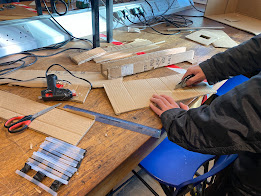
Then finally we designed a prototype of the carboard track for the ball in cardboard

Problems
The VL53L1X has very large conical shape of detection we did not realise it had. It is configurable in software but the smallest angle of detection in can go down to is 15 around 15 degrees. Due to the cone , the original U shape design of the track wouldn't be effective, as the sensor would just pick up all the readings from the inside walls of the of the U track. To fix this, we have shifted our focus
towards a more train track-like approach with two parallel wooden dowels.
Tasks for next week
- Order a AS5600 magnetic encoder to track position of the stepper to set endpoints
- Order long wooden dowels for the track
- Begin iterations of the mechanical linkages and system
Project Title - 1 Dimension Pid Ball Balancing System
Team Members - Samuel Frimpong /Yuhao Fang
Academic Advisor - Mohammad Hasan


Comments
Post a Comment