This weeks Activities
This week consisted of some out of lab work , as we had to start designing the prototypes for the mechanical side of the system. We first started by choose an arbitrary height for the motor arm linkage as this would allow us to build the rest of the system around it by choosing heights for the other components that would cause the beam to travel through our desired angle . We deducted that 225mm would be a good distance for the end of the effector to have relative to the centre of the motor at full extension . A standard 1 :2 linkage arm length ratio was also chosen to increase stability and grant finer control. A 1:2 ratio meant that the short am had a length of 75mm and the long one 150mm
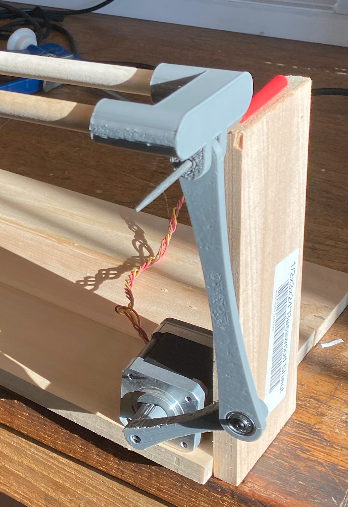
Next We moved on to the beam hinge mechanics. These are essentially the connectors that fit onto the ends of the track and connected the the fixed hinge rotation point and the end effector arm. Also note that we chose a bearing size of 624ZZ that glue into the bigger holes.
Finally we designed riser stands for the first for the fixed hinge and then for the final iteration, for the motor. We chose a triangular shape because of increased strength ,stability and looks:
All of the progress shown in these photos were from only the first iteration. All of these components went through various tweaks and fixes to make them more robust . We also designed these pieces to have easy assembly, and this made our testing much easier. After cutting the planks and dowels to required length ,the intermediate and final designs are shown below:
We then shifted our focus towards software. The as56000 encoder we had ordered last week arrived and so we tested it using demo software in the documentation. The as5600 is a magnetic encoder detects an absolute rotation angle by using a small magnet. This magnet is placed onto the shaft of the stepper with the as5600 mounted very closely behind it (1mm). This would allow us to set stepper angle limits when moving the arm later. After as assembling the final iteration , ran the stepper motor demo program to ensure that everything was working as theorized:
Challenges
The VL53L1X TOF sensor was not detecting the ball past a certain distance on the track initially. We discovered that one of the wooden dowels was slightly bowed , meaning that that ball wouldn't follow a straight path. The effect was exaggerated by the sensor also being slightly in the wrong position, angular and vertically. To address the bowed track, we designed a few braces to hold the track straight. To address the sensor position, we will need to design a new connector for that end that allows for the required flexibility
There is a difference in the intermediate design and the final design of the stands. In the intermediate design we used isosceles triangles where as in the final we used right angle. The is also a difference in screw hole placement. The right angle design allowed us to fit a considerably longer length of track onto a small base and the new screw placement allowed for less fiddly installation
Tasks for next week
- Redesign the TOF sensor for vertical and angular adjustability
- Order LCD FOR display status of pid values
- Order clickable rotary encoder to control hardware dynamically
- Start design of software
Project Title - 1 Dimension Pid Ball Balancing System
Team Members - Samuel Frimpong /Yuhao Fang
Academic Advisor - Mohammad Hasan


Comments
Post a Comment